User Interfaces Channel

The User Interfaces channel focuses on the issues affecting both the physical and logical trade-offs of integrating user interfaces into embedded designs to support making it easier for a user to correctly, consistently, and unambiguously control the behavior of the system.

Interface Transitions and Spatial Clues

Tuesday, November 8th, 2011 by Robert Cravotta

Every time I upgrade any of my electronic devices, there is a real risk that something in the user interface will change. This is true of not just updating software but also when updating hardware. While someone who is responsible for the update decided the change in the interface is an improvement over the old interface, there is often a jolt as established users either need to adjust to the change or the system provides mechanisms that support the older interface. Following are some recent examples I have encountered.

A certain browser for desktop computers has been undergoing regular automagical updates – among the recent updates is a shuffling of the menu bar/button and how the tabs are displayed within the browser. Depending on who I talk to, people either love or hate the change. Typically it is not that the new or old interface is better but that the user must go through the process of remapping their mental map of where and how to perform the tasks they need to do. For example, a new menu tree structure breaks many of the learned paths, the spatial mapping so to speak, to access and issue specific commands. This can result in a user not being able to easily execute a common command (such as clear temporary files) without feeling like they have to search for a needle in a haystack because their spatial mapping for a command needs to be remapped.

Many programs provide update/help pages to help with this type of transition frustration, but sometimes the update cycle for the program is faster than the frequency that a user may use a specific command, and this can cause further confusion as the information the user needs is buried in an older help file. One strategy to accommodate users is to allow them to explicitly choose which menu structure or display layout they want. The unfortunate thing about this approach is that it is usually an all or nothing approach. The new feature may only be available under the new interface structure. Another more subtle strategy that some programs use to accommodate users is to quietly support the old keystrokes while displaying the newer interface structure. This approach can work well for users that memorized keyboard sequences, but it does not help those users that manually traversed the menus with the mouse. Additionally, these approaches do not really help with transitioning to the new interface; rather, they enable a user to put off the day of reckoning a little longer.

My recent experience with a new keyboard and mouse provides some examples of how these devices incorporate spatial clues to improve the experience of adapting to these devices.

The new keyboard expands the number of keys available. Despite providing a standard QWERTY layout, the relative location of the keys on the left and right edge of the layout was different relative to the edge of the keyboard. At first, this caused me to hit the wrong key when I was trying to press keys around the corners and edges of the keyboard layout – such as the ctrl and the ~ keys. With a little practice, I no longer hit the wrong keys. It helps that the keys on the left and right edge of the layout are different shapes and sizes from the rest of the alphanumeric keys. The difference in shape helps provide immediate feedback of where my hands are within the spatial context of the keyboard.

Additionally, the different sets of keys are grouped together so that the user’s fingers can feel a break between the groupings and the user is able to identify which grouping their hands are over without looking at the keyboard. While this is an obvious point, it is one that contemporary touch interfaces are not able to currently accommodate. The keyboard also includes a lighting feature for the keys that allows the user to specify a color for the keyboard. My first impression was that this was a silly luxury, but it has proven itself a useful capability because it makes it possible to immediately and unambiguously know what context mode the keyboard is in (via different color assignments) so that the programmable keys can take on different functions with each context.

The new mouse expands on the one or two button capability by supporting more than a dozen buttons. I have worked with mice with many buttons before, and because of that, the new mouse had to have at least two thumb buttons. The new mouse though does a superior job not just with button placement, but in providing spatial clues that I have never seen on a mouse before. Each button on the mouse actually has a slightly different shape, size, and/or angle that it touches the user’s fingers. It is possible to immediately and unambiguously know which button you are touching without looking at the mouse. There is a learning curve to know how each button feels, but the end result is that all of the buttons are usable with a very low chance of pressing unintended buttons.

In many of the aerospace interfaces that I worked on, we placed different kinds of cages around the buttons and switches so that the users could not accidently flip or press one. By grouping the buttons and switches and using different kinds of cages, we were able to help the user’s hands learn how performing a given function should feel. This provided a mechanism to help the user detect when they might be making an accidental and potentially catastrophic input. Providing this same level of robustness is generally not necessary for consumer and industrial applications, but providing some level of spatial clues, either via visual cues or physical variations, can greatly enhance the user’s learning curve when the interface changes and provide clues when the user is accidently hitting an unintended button.

The State of Voice User Interfaces

Tuesday, September 20th, 2011 by Robert Cravotta

While touch interfaces have made a splash in the consumer market, voice-based user interfaces have been quietly showing up in more devices. Interestingly, voice user interfaces were expected to become viable long before touch interfaces. The technical challenges to implementing a successful speech recognition capability far exceeded what research scientists expected. That did not however stop story writers and film productions from adopting voice user interfaces in their portrayal of the future. Consider the ship’s computer in the Star Trek series. In addition to using proximity sensors that worked uncannily well in understanding when to open and close doors, the ship’s computer in Star Trek was able to tell when a person was issuing a request or command versus when they were just talking to another person.

Today, the quiet rise of speech recognition in consumer devices is opening up a different way to interact with devices – one that does not require the user to focus their eyes on a display to help them know where to place their fingertips to issues commands. Improving speech recognition technology is providing an alternative for interacting with devices for people with dyslexia. However, there are a number of subtle challenges facing systems that rely on speech recognition, and make it challenging to provide a reliable and robust voice user interface.

For a voice interface to be useful, there are a number of ambiguities the system must be able to clarify. In addition to accurately identifying what words are spoken, the system must be able to reliably filter out words that are not issued by the user. It also it must be able to distinguish between words from the user that are intended for the system versus those words intended for another person or device.

One way that systems enable a user to actively assist the speech recognition module to resolve these types of ambiguity is to force the user to press and/or hold a button indicating that they are issuing a voice command. By relying on an unambiguous input, such as a button press, the speech recognition module is able to leverage the system’s processing capacity at the time a command is most likely being issued. This approach supports a lower power operation because it enables the system to avoid operating in an always-on mode that can drain the system’s energy store.

The positive button press also prompts the user, even unconsciously, to make accommodations based on the environment they are talking. If the environment is noisy, users may move themselves to a quieter location, or position themselves so that the device microphone is shielded from the noise in the area, such as cupping the device with their hand or placing the device close to their mouth. This helps the system act more reliably in a noisy environment, but it relies on the user’s actions to improve the efficiency of the noise immunity. An ideal speech recognition module would have a high immunity to noisy environments while consuming a low amount of low energy without having to rely on the user.

But detecting when the user is speaking and issuing a command to the device is only the first step in implementing a viable voice user interface. Once the system has determined that the user is speaking a command, the system has four more steps to complete to close the loop between the system and the user. Following voice activation, the module needs to perform the actual speech recognition and transcription step. This stage of speech processing also relies on a high level of immunity to noise, but the noise immunity does not need to be as robust as it is for voice the activation stage because this stage of processing is only active when the system has already determined that the user is speaking a command. This stage of processing relies on high accuracy to successfully separate the user’s voice from the environmental noise and transcribing the sound waves into symbols that the rest of the speech module can use.

The third stage of processing takes the output of the transcribed speech and determines the intent and meaning of the speech so as to be able to accurately understand what the user is asking for. This stage of processing may be as simple as comparing the user’s input to a constrained set of acceptable words or phrases. If a match is found, the system acts on it. If no acceptable match is found, the system may prompt the user to reissue the command or ask the user to confirm the module’s guess of the user’s command.

For more sophisticated speech recognition, this stage of processing resolves ambiguity in the semantics of the issued command. This may involve considering each part of the speech in context with the whole message spoken by the user to identify contradictions that could signal an inappropriate way to interpret the user’s spoken words. If the system is able to process free form speech, it may rely on a significant knowledge of language structure to improve its ability to properly identify the meaning of the words the user actually spoke.

The next stage of processing involves acting on the issued command. Is the command a request for information? Is it a request to activate a component in the system? This processing performed during this stage is as varied as there are tasks that a system can perform. The final stage though is to ensure that there is appropriate feedback to the user that their command was received, properly interpreted, and the appropriate actions were started, in progress, or even completed. This might involve an audio tone, a haptic feedback, an audio acknowledgement, or even a change in the display.

There are a number of companies providing the technology to implement speech recognition in your designs. Two of them are Sensory and Nuance. Nuance provides software for speech recognition while Sensory provides both hardware and embedded software for speech recognition. Please share the names and links of any other companies that you know provide tools and resources for speech recognition in the comments.

Travelling the Road of Natural Interfaces

Thursday, July 28th, 2011 by Robert Cravotta

The forms for interfacing between humans and the machines are constantly evolving, and the creation rate of new forms for human-machine interfacing seems to be increasing. Long gone are the days of using punch cards and card reader to tell a computer what to do. Most contemporary users are unaware of what a command line prompt and optional argument is. Contemporary touch, gesture, stylus, and spoken language interfaces threaten to make the traditional hand shaped mouse a quaint and obsolete idea.

The road from idea, to experimental implementations, to production forms for human interfaces usually spans many attempts over years. For example, the first computer mouse prototype was made by Douglas Engelbart, with the assistance of Bill English, at the Stanford Research Institute in 1963. The computer mouse became a public term and concept around 1965 when it was associated to a pointing device in Bill English’s publication of “Computer-Aided Display Control.” Even though the mouse was available as a pointing device for decades, it finally became a ubiquitous pointing device with the release of Microsoft Windows 95. The sensing mechanisms for the mouse pointer evolved though mechanical methods using wheels or balls to detect when and how the user moved the mouse. The mechanical methods have been widely replaced with optical implementations based around LEDs and lasers.

3D pointing devices started to appear in market the early 1990’s, and they have continued to evolve and grow in their usefulness. 3D pointing devices provide positional data along at least 3 axes with contemporary devices often supporting 6 degrees of freedom (3 positional and 3 angular axes). Newer 9 degrees of freedom sensors (the additional 3 axes are magnetic compass axes), such as from Atmel, are approaching integration levels and price points that practically ensure they will find their way into future pointing devices. Additional measures of sensitivity for these types of devices may include temperature and pressure sensors. 3D pointing devices like Nintendo’s Wii remote combine spatial and inertial sensors with vision sensing in the infrared spectrum that relies on a light bar with two infrared light sources that are spaced at a known distance from each other.

Touch Interfaces

The release of Apple’s iPhone marked the tipping point for touch screen interfaces. However, the IBM Simon smartphone predates the iPhone by nearly 14 years, and it sported similar, even if primitive, support for a touchscreen interface. Like many early versions of human-machine interfaces that are released before the tipping point of market acceptance, the Simon did not enjoy the same market wide adoption as the iPhone.

Touchscreen interfaces span a variety of technologies including capacitive, resistive, inductive, and visual sensing. Capacitive touch sensing technologies, along with the software necessary to support these technologies, are offered by many semiconductor companies. The capacitive touch market has not yet undergone the culling that so many other technologies experience as they mature. Resistive touch sensing technology has been in production use for decades and many semiconductor companies still offer resistive touch solutions; there remain opportunities for resistive technologies to remain competitive with capacitive touch into the future by harnessing larger and more expensive processors to deliver better signal-to-noise performance. Vision based touch sensing is still a relatively young technology that exists in higher-end implementations, such as the Microsoft Surface, but as the price of the sensors and compute performance needed to use vision-based sensing continues to drop, it may move into direct competition with the aforementioned touch sensing technologies.

Touch interfaces have evolved from the simple drop, lift, drag, and tap model of touch pads to supporting complex multi-touch gestures such as pinch, swipe, and rotate. However, the number and types of gestures that touch interface systems can support will explode in the near future as touch solutions are able to continue to ride Moore’s law and push more compute processing and gesture databases into the system for negligible additional cost and energy consumption. In addition to gestures that touch a surface, touch commands are beginning to be able to incorporate proximity or hovering processing for capacitive touch.

Examples of these expanded gestures include using more than two touch points, such as placing multiple fingers from one or both hands on the touch surface and performing a personalized motion. Motions can consist of nearly any repeatable motion, including time sensitive swipes and pauses, and it can be tailored for each individual user. As the market moves closer to a cloud computing and storage model, this type of individual tailoring becomes even more valuable because the cloud will enable a user to untether themselves from a specific device and access their personal gesture database on many different devices.

Feedback latency to the user is an important measurement and a strong limiter on the adoption rate of expanded human interface options that include more complex gestures and/or speech processing. A latency target of about 100ms has consistently been the basic advice for feedback responses for decades (Miller, 1968; Myers 1985; Card et al. 1991) for user interfaces; however, according to the Nokia Forum, for tactile responses, the response latency should be kept under 20ms or the user will start to notice the delay between a user interface event and the feedback. Staying within these response time limits affects how complicated a gesture a system can handle and provide satisfactory response times to the user. Some touch sensing systems can handle single touch events satisfactorily but can, under the right circumstances, cross the latency threshold and become inadequate for handling two touch gestures.

Haptic feedbacks provide a tactile sensation, such as a slight vibration, to the user to provide immediate acknowledgement that the system has registered an event. This type of feedback is useful in noisy environments where a sound or beep is insufficient, and it can allow the user to operate the device without relying on visual feedback. An example is when a user taps a button on the touch screen and the system signals the tap with a vibration. The forum goes on to recommend that the tactile feedback is not exaggerated and short (less than 50ms) so as to keep the sensations pleasant and meaningful to the user. Vibrating the system too much or often makes the feedback meaningless to the user and risks draining any batteries in the system. Tactile feedbacks should also be coupled with visual feedbacks.

Emerging Interface Options

An emerging tactile feedback involves simulating texture on the user’s fingertip (Figure 1). Tesla Touch is currently demonstrating this technology that does not rely on mechanical actuators typically used in haptic feedback approaches. The technology simulates textures by applying and modulating a periodic electrostatic charge across the touch surface. By varying the sign (and possibly magnitude) of the charge, the electrons in the user’s fingertip will be drawn towards or away from the surface – effective creating a change in friction on the touch surface. Current prototypes are able to use signals as low as 8V to generate tactile sensations. No electric charge passes through the user.

Pranav Mistry at Fluid Interfaces Group | MIT Media Lab has demonstrated a wearable gesture interface setup combines digital information with the physical world through hand gestures and a camera sensor. The project is built with commercially available parts consisting of a pocket projector, a mirror, and a camera. The current prototype system costs approximate $350 to build. The projector projects visual information on surfaces, such as walls and physical objects within the immediate environment. The camera tracks the user’s hand gestures and physical objects. The software program processes the camera video stream and tracks the locations of the colored markers at the tip of the user’s fingers. Interpreted hand gestures act commands for projector and digital information interfaces.

Another researcher/designer is Fabian Hemmert whose projects explore emerging haptic feedback techniques including shape-changing and weight-shifting devices. His latest public projects include adding friction to a to a touch screen stylus that works through the stylus rather than through the user’s fingers like the Tesla Touch approach. The thought is that the reflective tactile feedback can prioritize displayed information, providing inherent confirmation of a selection by making the movement of the stylus heavier or lighter, and taking advantage of the manual dexterity of the user and providing friction that is similar to writing on a surface – of which the user is already familiar with.

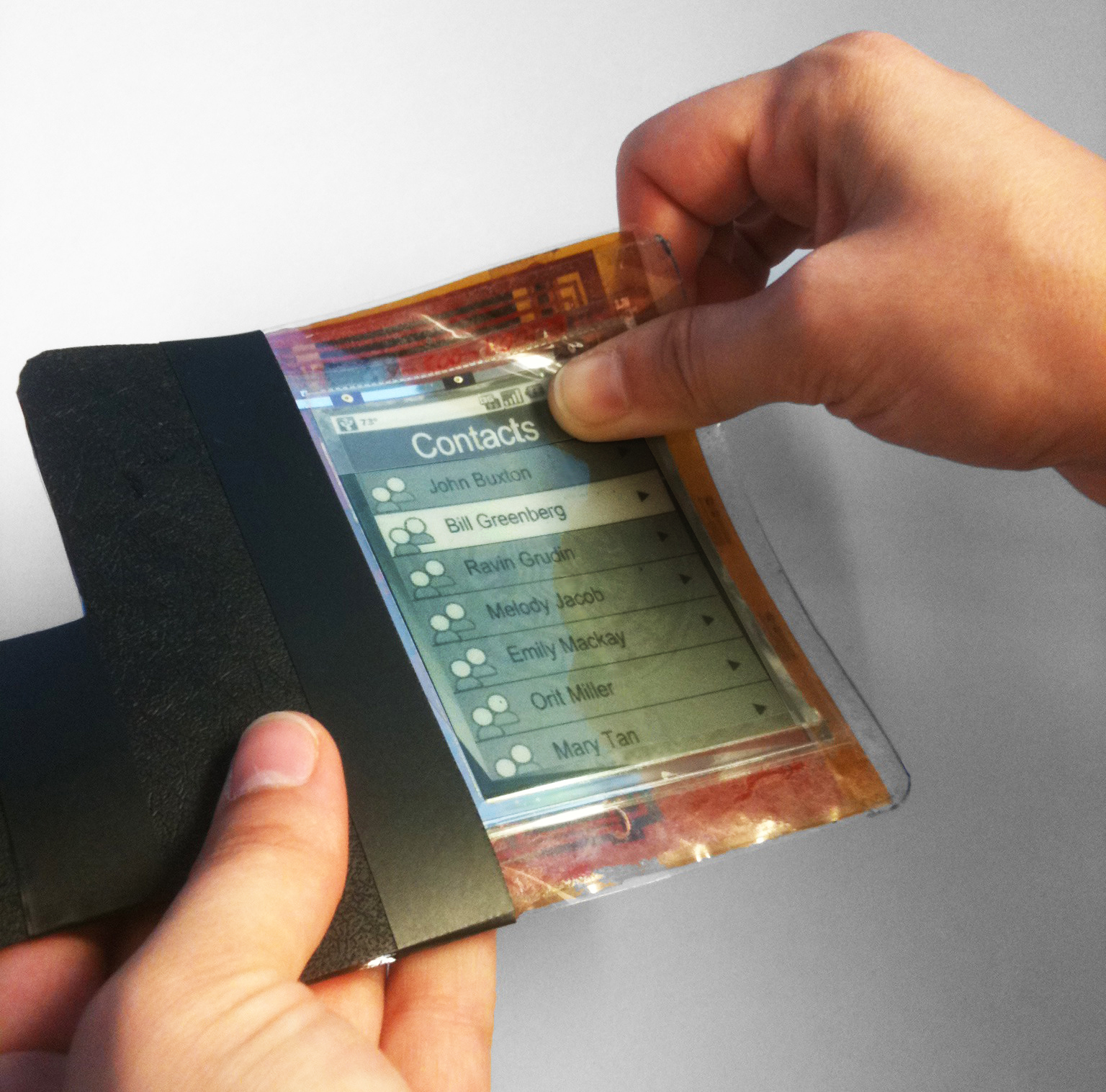
Human media Lab recently unveiled and is demonstrating a “paper bending” interface that takes advantage of E-ink’s flexible display technology (Figure 2). The research team suggests that bending a display, such as to page forward, shows promise as an interaction mechanism. The team identified six simple bend gestures, out of 87 possible, that users preferred based around bending forward or backwards at two corners or the outside edge of the display. The research team identifies potential uses for bend gestures when the user is wearing gloves that inhibit interacting with a touch screen. Bend gestures may also prove useful to users that have motor skill limitations that inhibit the use of other input mechanisms. Bend gestures may be useful as a means to engage a device without require visual confirmation of an action.

In addition to supporting commands that are issued via bending the display, the approach allows a single display to operate in multiple modes. The Snaplet project is a paper computer that can act as a watch and media player when wrapped like a bracelet on the user’s arm. It can function as a PDA with notepad functionality when held flat, and it can operate as a phone when held in a concave shape. The demonstrated paper computer can accept, recognize, and process touch, stylus, and bend gestures.

If the experiences of the computer mouse and touch screens are any indication of what these emerging interface technologies are in for, there will be a number of iterations for each of these approaches before they evolve into something else or happen upon the proper mix of technology, low cost and low power parts, sufficient command expression, and acceptable feedback latency to hit the tipping point of market adoption.

Requirements for tablet handwriting input

Monday, July 11th, 2011 by Guillaume Largillier

The market for tablet computers is exploding, with an estimated 100 million units that will be in use by 2013. The tablet form factor is very compelling because of its small size, light weight, and long battery life. Also, tablet operating systems, like Android, MeeGo, and iOs, have been designed so the input mechanism is touch-oriented, making their applications fun and easy to use.

One such tablet, the Apple iPad, has been a phenomenal success as a media-consumption device for watching movies, reading e-mail, surfing the Web, playing games, and other activities. But one thing is missing to make it the only device you need when going on a business trip: pen input. Pen input facilitates handwriting and drawing, which is important because our brain connectivity and the articulation in our arms, elbows, wrists, and fingers give us much greater motor skills when we use a tool. Everybody needs a pen, including children learning how to draw and write, engineers sketching a design, and business people annotating a contract.

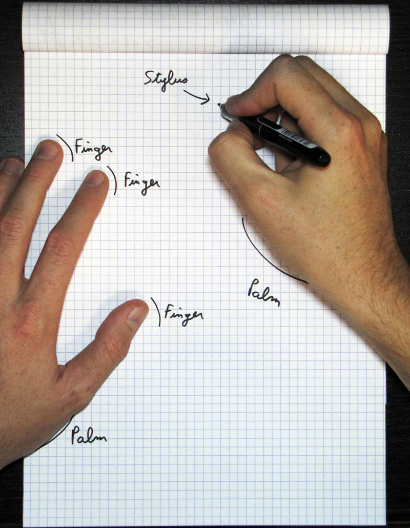
Natural handwriting involves many contact points to be discriminated.

Accordingly, the ultimate goal for tablet designers should be to replicate the pen-and-paper experience. Pen and paper work so well together: resolution is high, there is no lag between the pen movement and the depositing of ink, and you can comfortably rest your palm on the paper, with its pleasing texture.

These qualities, however, are not easy to replicate in a tablet computer. You need high responsiveness, high resolution, good rendering, and palm rejection. Writing on a piece of glass with a plastic stylus is not an especially pleasing experience, so you also need coating on the glass and a shape and feel of a stylus that can approximate the pen and paper experience. Most importantly, you need an operating system and applications that have been designed from the ground up to integrate this input approach.

A key part of the equation is multi-touch technology that knows whether a particular finger touching the device is merely holding it or activating a menu, whether a certain contact point is a finger or a stylus, and, more importantly, it needs to distinguish a palm resting on the top of the display so a user can comfortably write on the device. In short, handwriting on a tablet computer doesn’t require multi-touch per se but smart detection of what’s happening on the screen.

The typical iVSM layout

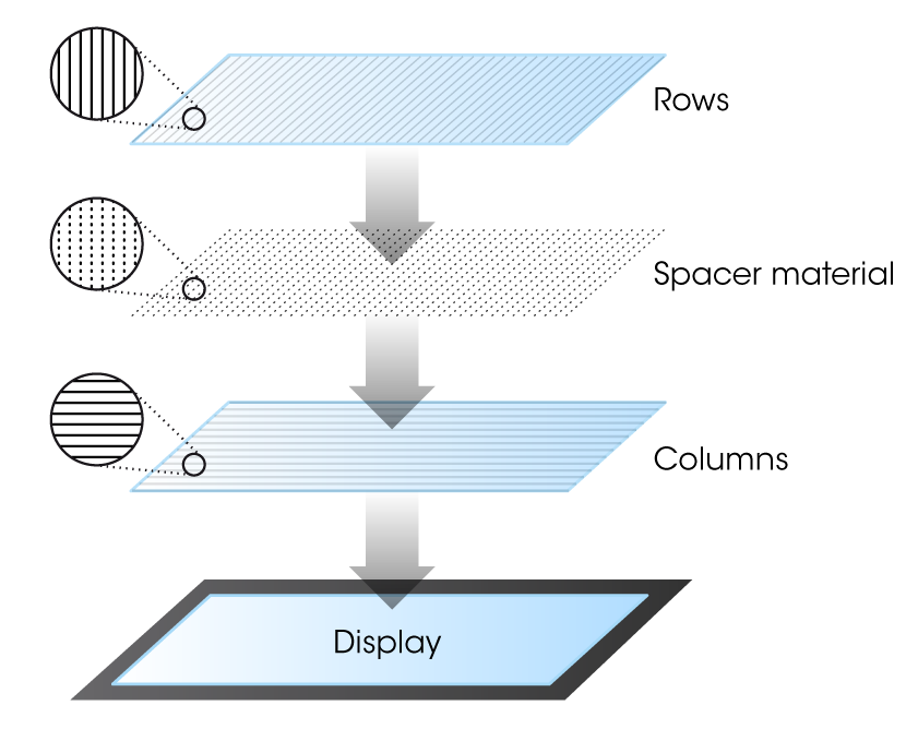
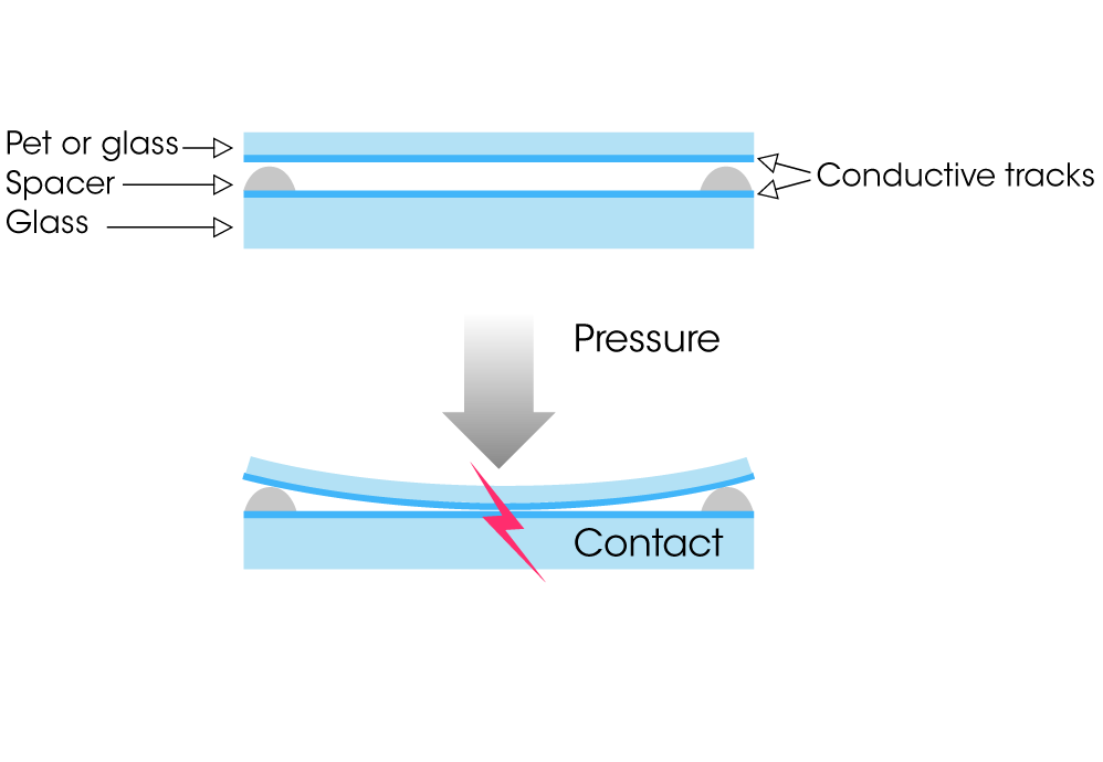
Interpolated voltage sensing matrix (iVSM) is a multi-touch technology that provides smart detection, including handwriting rendering and palm rejection. It can allow users to simultaneously move a pen or a stylus (and an unlimited number of fingers) on a screen. iVSM is similar to projected capacitive technology, as it employs conductive tracks patterned on two superimposed substrates (made of glass or hard plastic). When the user touches the sensor, the top layer slightly bends, enabling electrical contact between the two patterned substrates at the precise contact location (Figure 3). A controller chip scans the whole matrix to detect such contacts, and will track them to deliver cursors to the host. However, whereas capacitive technology relies on proximity sensing, iVSM is force activated, enabling it to work with a pen, a stylus, or any number of implements. 

iVSM layout cut view

The tablet computer revolution is well underway around the world, with handwriting becoming an increasingly necessary function. Accordingly, device designers and vendors should take proper heed, or they might soon be seeing the handwriting on the wall.

Touch me (too) tender

Tuesday, June 28th, 2011 by Robert Cravotta

A recent video of a fly activating commands on a touchscreen provides an excellent example of a touchscreen implementation that is too sensitive. In the video, you can see the computing system interpreting the fly’s movements as finger taps and drags. Several times the fly’s movement causes sections of text to be selected and another time you can see selected text that is targeted for a drag and drop command. Even when the fly just momentarily bounces off the touchscreen surface, the system detects and recognizes that brief contact as a touch command.

For obvious reasons, such over sensitivity in a touchscreen application is undesirable in most cases – that is unless the application is to detect and track the behavior of flies making contact with a surface. The idea that a fly could accidentally delete your important files or even send sensitive files to the wrong person (thanks to field auto-fill technology) is unpleasant at best.

Touchscreens have been available as an input device for decades, so why is the example of a fly issuing commands only surfacing now? First, the fly in the video is walking and landing on a capacitive touchscreen. Capacitive touch screens became more prevalent in consumer products after the launch of the Apple iPhone in 2007. Because capacitive touch screens rely on the conductive properties of the human finger, a touch command does not necessarily require a minimum amount of physical force to activate.

This contrasts with resistive touch screens which do require a minimum amount of physical force to cause two layers on the touch screen surface to make physical contact with each other. If the touch sensor in the video was a screen with a resistive touch sensor layered over it, the fly would most likely never be able to cause the two layers to make contact with each other by walking across the sensor surface; however, it might be able to make the surfaces contact each other if it forcefully collided into the screen area.

Touchscreens that are too sensitive are analogous to keyboards that do not implement an adequate debounce function for the keys. In other words, there are ways that capacitive touch sensors can mitigate spurious inputs such as flies landing on the sensor surface. There are two areas within the sensing system that a designer can work with to filter out unintended touches.

The first area to address in the system is to properly set the gain levels so that noise spikes and small conductive objects (like the feet and body of a fly) do not trigger a count threshold that would be interpreted as a touch. Another symptom of an oversensitive capacitive touch sensor is that it may classify a finger hovering over the touch surface as a touch before it makes contact with the surface. Many design specifications for touch systems explicitly state an acceptable distance above the touch surface that can be recognized as a touch (on the order of a fraction of a mm above the surface). I would share a template for specifying the sensitivity of a touch screen, but the sources I checked with consider that template proprietary information.

One reason why a touch system might be too sensitive is because the gain is set too high so as to allow the system to recognize when the user is using a stylus with a small conductive material within its tip. A stylus tip is sufficiently smaller than a human finger, and without the extra sensitivity in the touch sensor, a user will not be able to use a stylus because the sensor will fail to detect the stylus tip near the display surface. Another reason a touch system could be too sensitive is to accommodate a use-case that involves the user wearing gloves. In essence, the user’s finger never actually makes contact with the surface (the glove does), and the sensor system must be able to detect the finger through the glove even though it is hovering over the touch surface.

The other area of the system a designer should address to mitigate spurious and unintended touches is through shape processing. Capacitive touch sensing is similar to image or vision processing in that the raw data consists of a reading for each “pixel” in the touch area for each cycle or frame of input processing. In addition to looking for peaks or valleys in the pixel values, the shape processing can compare the shape of the pixels around the peak/valley to confirm that it is a shape and size that is consistent with what it expects. Shapes that are outside the expected set, such as six tiny spots that are close to each other in the shape of a fly’s body, can be flagged and ignored by the system.

This also suggests that the shape processing should be able to track context because it needs to be able to remember information between data frames and track the behavior of each blob of pixels to be able to recognize gestures such as pinch and swipe. This is the basis of cheek and palm rejection processing as well as ignoring a user’s fingers that are gripping the edge of the touch display for hand held devices.

One reason why a contemporary system, such as the one in the video, might not properly filter out touches from a fly is that the processor bandwidth of the processing used for the shape processing algorithm could not perform the more complex filtering in the time frame allotted. In addition to actually implementing additional code to handle more complex tracking and filtering, the system has to allocate enough processing resources to complete those tasks. As the number of touches that the controller can detect and track increases, the amount of processing required to resolve all of those touches goes up faster than linearly. Part of the additional complexity for complex shape processing comes from determining which blobs are associated with other blobs and which ones are independent from the others. This correlation function requires multi-frame tracking.

This video is a good reminder that what is good enough in the lab might be completely insufficient in the field.

An interface around the bend

Tuesday, May 24th, 2011 by Robert Cravotta

User interface options continue to grow in richness of expression as sensor and compute processing costs and energy requirements continue to drop. The “paper” computing device is one such example, and it hints that touch interfaces may only be the beginning of where user interfaces are headed. Flexible display technologies like E-Ink’s have supported visions of paper computers and hand held computing devices for over a decade. A paper recently released by Human Media Lab explores the opportunities and challenges of supporting user gestures that involve bending the device display similar to how you would bend a piece of paper. A video of the flexible prototype paper phone provides a quick overview of the project.

The paper phone prototype provides a demonstration platform for exploring gestures that involve the user bending the device to issue a command.

The demonstration device is based on a flexible display prototype called paper phone (see Figure). The 3.7” flexible electrophoretic display is coupled with a layer of five Flexpoint 2” bidirectional bend sensors that are sampled at 20Hz. An E-Ink Broadsheet AM 300 Kit with a Gumstix processor that is capable of completing a display refresh in 780ms for a typical full screen grey scale image. The prototype is connected to a laptop computer that offloads the processing for the sensor data, bend recognition, and sending images to the display to support testing the flexibility and mobility characteristics of the display.

The paper outlines how the study extends prior work with bend gestures in two important ways: 1) the display provided direct visual feedback to the user’s bend commands, and 2) the flexible electronics of the bending layer provided feedback. The study involved two parts. The first part asked the participants to define eight custom bend gesture pairs. Gestures were classified according to two characteristics based on the location of the force being exerted on the display and the polarity of that force. The configuration of the bend sensors supported recognizing folds or bends at the corners and along the center edge of the display. The user’s folds could exert force forward or backwards at each of these points. Gestures could consist of folding the display in a single location or at multiple locations. The paper acknowledges that there are other criteria they could have used, such as the amount of force in a fold, the number of repetitions of a fold, as well as tracking the velocity of a fold. These were not investigated in this study.

The second part of the study asked participants to use and evaluate the bend gestures they developed in the context of complete tasks, such as operating a music player or completing a phone call. The study found that there was strong agreement among participants for the folding locations as well as the polarity of the folds for actions with clear directionality, such as navigating left and right. The applications that the participants were asked to complete were navigating between twelve application icons; navigating a contact list; play, pause, and select a previous or next song; navigate a book reader, and zoom in and out for map navigation. The paper presents analysis of the 87 total bend gestures that the ten participants created (seven additional bends were created in the second part of the study) in building a bend gesture/language, and it discusses shared preferences among the participants.

A second paper from Human Media Lab presents a demonstration “Snaplet” prototype for a bend sensitive device to change its function and context based on its shape. The video of the Snaplet demonstrates the different contexts that the prototype can recognize and adjust to. Snaplet is similar to the paper phone prototype in that it uses bend sensors to classify the shape of the device. Rather than driving specific application commands with bends, deforming the shape of the device drives which applications the device will present to the user and what types of inputs it will accept and use. The prototype includes pressure sensors to detect touches, and it incorporates a Wacom flexible tablet to enable interaction with a stylus. Deforming the shape of the device is less dynamic than bending the device (such as in the first paper); rather the static or unchanging nature of the deformations allows the device’s shape to define what context it will work in.

When the Snaplet is bent in a convex shape, such as a wristband on the user’s arm, Snaplet acts like a watch or media player. The user can place the curved display on their arm and hold in in place with Velcro. The video of the Snaplet shows the user interacting with the device via a touch screen with icons and application data displayed appropriately for viewing on the wrist. By holding the device flat in the palm of their hand, the user signals to the device that it should act as a PDA. In this context, the user can use a Wacom stylus to take notes or sketch; this form factor is also good for reading a book. The user can signal the device to act as a cell phone by bending the edge of the display with their fingers and then placing the device to their ear.

Using static bends provides visual and tangible cues to the user of the device’s current context and application mode. Holding the device in a concave shape requires a continuous pinch from the user and provides haptic feedback that signifies there is an ongoing call. When the user releases their pinch of the device, the feedback haptic energy directly corresponds with dropping the call. This means that users can rely on the shape of the device to determine its operating context without visual feedback.

The paper phone and Snaplet prototypes are definitely not ready for production use, but they are good demonstration platforms to explore how and when using bend gestures and deforming the shape of a device may be practical. Note that these demonstration platforms for these types of inputs do not suggest replace existing forms of user interfaces, such as touch and stylus inputs; rather, they demonstrate how bend gestures can augment those input forms and provide a more natural and richer communication path with electronic devices.

The battle for multi-touch

Tuesday, April 12th, 2011 by Robert Cravotta

As with most technologies used in the consumer space, they take a number of years to gestate before they mature enough and gain visibility to end users. Capacitive-based multi-touch technology burst into the consumer conscience with the introduction of the iPhone. Dozens of companies have since entered the market to provide capacitive touch technologies to support new designs and applications. The capabilities that capacitive touch technology can support, such as improved touch sensing for multiple touches, detecting and filtering unintended touches (such as palm and cheek detection), as well as supporting a stylus, continues to evolve and improve.

Capacitive touch enjoys a very strong position providing the technology for multi-touch applications; however, there are other technologies that are or will likely be vying for a larger piece of the multi-touch pie. A potential contender is the vision-based multi-touch technology found in the Microsoft Surface. However, at the moment of this writing, Microsoft has indicated that it is not focusing its effort for the pixel sense technology toward the embedded market, so it may be a few years before the technology is available to embedded developers.

The $7600 price tag for the newest Surface system may imply that the sensing technology is too expensive for embedded systems, but it is important to realize that this price point supports a usage scenario that vastly differs from a single user device. First, the Surface provides a 40 inch diagonal touch/display surface that four people can easily access and use simultaneously. Additionally, the software and processing resources contained within the system are sized to handle 50 simultaneous touch points. Shrink both of these capabilities down to a single user device and the pixel sense technology may become quite price competitive.

Vision-based multi-touch works with more than a user’s fingers; it can also detect, recognize and interact with mundane, everyday objects, such as pens, cups, paint brushes, as well as touch interface specific objects such as styli. The technology is capable, if you provide enough compute capability, to distinguish and handle touches and hovering of fingers and objects over the touch surface differently.I’m betting as the manufacturing process for the pixel sense sensors matures, the lower price points will make a compelling case for focusing development support to the embedded community.

Resistive touch technology is another multi-touch contender. It has been the work horse for touch applications for decades, but its ability (or until recently, lack of) to support multi-touch designs has been one of its significant shortcomings. One advantage that resistive touch has enjoyed over capacitive touch for single-touch applications is a lower cost point to incorporate it into a design. Over the last year or so, resistive touch has evolved to be able to support multi-touch designs by using more compute processing in the sensor to resolve the ghosting issues in earlier resistive touch implementations.

Similar to vision-based multi-touch, resistive touch is able to detect contact with any normal object because resistive touch relies on a mechanical interface. Being able to detect contact with any object provides an advantage over capacitive touch because capacitive touch sensing can only detect objects, such as a human finger or a special conductive-tipped stylus, with conductive properties that can draw current from the capacitive field when placed on or over the touch surface. Capacitive touch technology also continues to evolve, and support for thin, passive styli (with an embedded conductive tip) is improving.

Each technology offers different strengths and capabilities; however, the underlying software and embedded processors in each approach must be able to perform analogous functions in order to effectively support multi-touch applications. A necessary capability is the ability to distinguish between explicit and unintended touches. This capability requires the sensor processor and software to be able to continuously track many simultaneous touches and assign a context to each one of them. The ability to track multiple explicit touches relative to each other is necessary to be able to recognize both single- and multi-touch gestures, such as swipes and pinches. Recognizing unintended touches involves properly ignoring when the user places their palm or cheek over the touch area as well as touching the edges of the touch surface with their fingers that are gripping the device.

A differentiating capability for touch sensing is minimizing the latency between when the user makes an explicit touch and when the system responds or provides the appropriate feedback to that touch. Longer latencies can affect the user’s experience in two detrimental ways in that the collected data for the touch or gesture has poor quality or the delay in feedback confuses the user. One strategy to minimize latency is to sample or process less points when a touch (or touches) is moving; however, this risks losing track of small movements that can materially affect analyzing the user’s movement such as when writing their signature. Another strategy to accommodate tracking the movement of a touch without losing data is to allow a delay in displaying the results of the tracking. If the delay is too long though, the user may try to compensate and try to restart their movement – potentially confusing or further delaying the touch sensing algorithms. Providing more compute processing helps in both of these cases, but it also increases the cost and energy draw of the system.

While at CES, I experienced multi-touch with all three of these technologies. I was already familiar with the capabilities of capacitive touch. The overall capabilities and responsiveness of the more expensive vision-based system met my expectations; I expect the price point for vision-based sensing to continue its precipitous fall into the embedded space within the next few years. I had no experience with resistive-based multi-touch until the show. I was impressed by the demonstrations that I saw from SMK and Stantum. The Stantum demonstration was on a prototype module, and I did not even know the SMK module was a resistive based system until the rep told me. The pressure needed to activate a touch felt the same as using a capacitive touch system (however, I am not an everyday user of capacitive touch devices). As these technologies continue to increasingly overlap in their ability to detect and appropriately ignore multiple touches within a meaningful time period, their converging price points promise an interesting battle as each technology finds its place in the multi-touch market.

Touch with the Microsoft Surface 2.0

Tuesday, March 29th, 2011 by Robert Cravotta

The new Microsoft Surface 2.0 will become available to the public later this year. The technology has undergone significant changes from when the first version was introduced in 2007. The most obvious change is that the dimensions of the newer unitis much thinner, so much so, that the 4 inch thick display can be wall mounted – effectively enabling the display to act like a large-screen 1080p television with touch capability.Not only is the new display thinner, but the list price has nearly halved to $7600. While the current production versions of the Surface are impractical for embedded developers, the sensing technology is quite different from other touch technologies and may represent another approach to user touch interfaces that will compete with other forms of touch technology.

Namely, the touch sensing in the Surface is not really based on sensing touch directly – rather, it is based on using IR (infrared) sensors the visually sense what is happening around the touch surface. This enables the system to sense and be able to interact with nearly any real world object, not just conductive surfaces such as with capacitive touch sensing or physical pressure such as with resistive touch sensing. For example, there are sample applications of the Surface working with a real paint brush (without paint on it). The system is able to identify objects with identification markings, in the form of a pattern of small bumps, to track those objects and infer additional information about them that other touch sensing technologies currently cannot do.

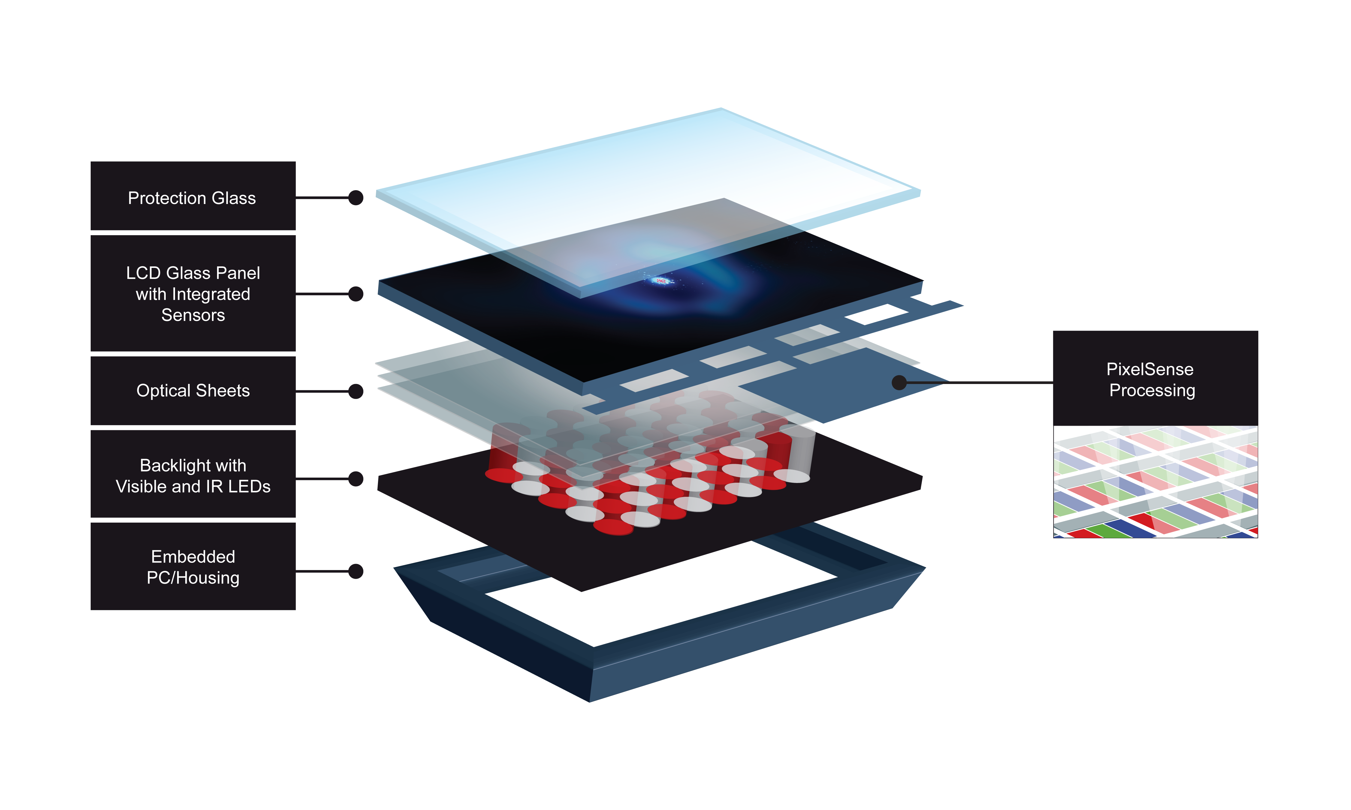
This exploded view of the Microsoft Surface illustrate the various layers that make up the display and sensing housing of the end units. The PixelSense technology is embedded into the LCD layers of the display.

The vision sensing technology is called PixelSense Technology, and it is able to sense the outlines of objects that are near the touch surface and distinguish when they are touching the surface. Note: I would include a link to the PixelSense Technology at Microsoft, but it is not available at this time. The PixelSense Technology embedded in the Samsung SUR40 for Microsoft Surface replaces the five (5) infrared cameras that the earlier version relies on. The SUR40 for Microsoft Surface is the result of a collaborative development effort between Samsung and Microsoft. Combining the Samsung SUR40 with Microsoft’s Surface Software enables the entire display to act as a single aggregate of pixel-based sensors that are tightly integrated with the display circuitry. This shift to an integrated sensor enables the finished casing to be substantially thinner than previous versions of the Surface.

The figure highlights the different layers that make up the display and sensing technology. The layers are analogous to any LCD display except that the PixelSense sensors are embedded in the LCD layer and do not affect the original display quality. The optical sheets include material characteristics to increase the viewing angle and to enhance the IR light transmissivity. PixelSense relies on the IR light generated at the backlight layer to detect reflections from objects above and on the protection layer. The sensors are located below the protection layer.

The Surface software targets an embedded AMD Athlon II X2 Dual-Core Processor operating at 2.9GHz and paired with an AMD Radeon HD 6700M Series GPU using DirectX 11 acting as the vision processor. Applications use an API (application program interface) to access the algorithms contained within the embedded vision processor. In the demonstration that I saw of the Surface, the system fed the IR sensing to a display where I could see my hand and objects above the protection layer. The difference between an object hovering over and touching the protection layer is quite obvious. The sensor and embedded vision software are able to detect and track more than 50 simultaneous touches. Supporting the large number of touches is necessary because the use case for the Surface is to have multiple people issuing gestures to the touch system at the same time.

This technology offers exciting capabilities for end-user applications, but it is currently not appropriate, nor available, for general embedded designs. However, as the technology continues to evolve, the price should continue to drop and the vision algorithms should mature so that they can operate more efficiently with less compute performance required of the vision processors (most likely due to specialized hardware accelerators for vision processing). The ability to be able to recognize and work with real world objects is a compelling capability that the current touch technologies lack and may never acquire. While the Microsoft person I spoke with says the company is not looking at bringing this technology to applications outside the fully integrated Surface package, I believe the technology will become more compelling for embedded applications sooner rather than later. At that point, experience with vision processing (different from image processing) will become a valuable skillset.

How to add color to electronic ink

Tuesday, February 15th, 2011 by Robert Cravotta

Over the past few years, electronic ink has been showing up in an increasing number of end-user products. Approximately ten years ago, there were a couple of competing approaches to implementing electronic ink, but E-Ink’s approach has found the most visible success of moving from the lab and viably existing in production level products, such as e-readers, indicators for USB sticks or batteries, as well as watch, smart card, and retail signage displays.

As a display technology, electronic ink exhibits characteristics that distinguish it from active display technologies. The most visible difference is that electronic ink exhibits the same optical characteristics as the printed page. Electronic ink displays do not require back or front lights; rather, they rely on reflecting ambient light with a minimum of 40% reflectivity. This optical quality contributes to a wider viewing angle (almost 180 degrees), better readability over a larger range of lighting conditions (including direct sunlight), and lower energy consumption because the only energy consumed by the display is to change the state of each pixel. Once an image is built on a display, it will remain there until there is another electrical field applied to the display – no energy is consumed to maintain the image. The switching voltage is designed around +/- 15 V.

However, electronic ink is not ideal for every type of display. The 1 to 10 Hz refresh rate is too slow for video. Until recently, electronic ink displays only supported up to 16 levels of grey scale monochrome text and images. The newest electronic ink displays now support up to 4096 colors (with 4-bit CR bias) along with the 16 levels of grey scale. Interestingly, adding support for color does not fundamentally change the approached used to display monochrome images.

The pigments and the chemistry are exactly the same between monochrome and color display; however, the display structure itself is different. The display is thinner so that it can be closer to a touch sensor to minimize parallax error that can occur based on the thickness of the glass over the display (such as with an LCD). Additionally, the display adds a color filter layer on the display and refines the process for manipulating the particles within each microcapsule.

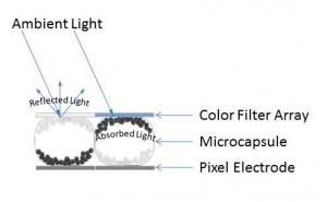
The positively charged white particles reflect light while the negatively charged black particles absorb light.

The 1.2 mm thick electronic ink display consists of a pixel electrode layer, a layer of microcapsules, and a color filter array (Figure 1). The electrode layer enables the system to attract and repel the charged particles within each of the microcapsules to a resolution that exceeds 200 DPI (dots per inch). Within each microcapsule are positively charged white particles and negatively charged black particles which are all suspended within a clear viscous fluid. When the electrode layer applies a positive or negative electric field near each microcapsule, the charged particles within it move to the front or back of the microcapsule depending on whether it is attracted or repelled from the electrode layer.

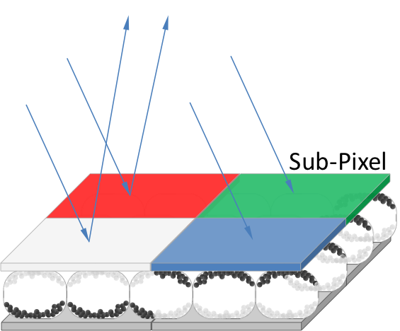
When the white particles are at the top of the microcapsule, the ambient light is reflected from the surface of the display. Likewise, when the black particles are at the top of the microcapsule, the ambient light is absorbed. Note that the electrode does not need to align with each microcapsule because the electric field affects the particles within the microcapsule irrespective of the border of the capsule; this means that a microcapsule can have white and black particles at the top of the capsule at the same time (Figure 2). By placing a color filter array over the field of microcapsules, it becomes possible to select which colors are visible by moving the white particles under the appropriate color segments in the filter array. Unlike the microcapsule layer, the electrode layer does need to tightly correlate with the color filter array.

The color filter array consists of a red, green, blue, and white sub-pixel segment at each pixel location. Controlling the absorption or reflection of light at each segment yields 4096 different color combinations.

This display uses an RGBW (Red, Green, Blue, and White) color system that delivers a minimum contrast ratio of 10:1 (Figure 2). For example, to show red, you would bring the white particles forward in the microcapsules under the red segment of the filter array while bringing the black particles forward in the other segments of the array. To present a brighter red color, you can also bring the white particles forward under the white segment of the filter array – however, the color will appear less saturated. To present a black image, the black particles are brought forward under all of the color segments. To present a white image, the white particles are brought forward under all of the color segments because under the RGBW color system, white is the result of all of the colors mixed together.

As electronic ink technology continues to mature and find a home in more applications, I expect that we will see developers take advantage of the fact that these types of displays can be formed into any shape and can be bent without damaging them. The fact that the color displays rely on the same chemistry as the monochrome ones suggests that adding color to a monochrome-based application should not represent a huge barrier to implement. However, the big challenge limiting where electronic ink displays can be used is how to implement the electrode layer such that it still delivers good enough resolution in whatever the final shape or shapes the display must support.

Looking at Tesla Touch

Friday, January 14th, 2011 by Robert Cravotta

The team at Disney Research has been working on the Tesla Touch prototype for almost a year. Tesla Touch is a touchscreen feedback technology that relies on the principles of electrovibration to simulate textures on a user’s fingertips. This article expands on the overview of the technology I wrote earlier, and it is based on a recent demonstration meeting at CES that I had with Ivan Poupyrev and Ali Israr, members of the Tesla Touch development team.

The first thing to note is that the Tesla Touch is a prototype; it is not a productized technology just yet. As with any promising technology, there are a number of companies working with the Tesla Touch team to figure out how they might integrate the technology into their upcoming designs. The concept behind the Tesla Touch is based on technology that researchers in the 1950’s were working on to assist blind people. The research fell dormant and the Tesla Touch team has revived it. The technology shows a lot of interesting promise, but I suspect the process of making it robust enough for production designs will uncover a number of use-case challenges (like it probably did for the original research team).

The Tesla Touch controller modulates a periodic electrostatic charge across the touch surface which attracts and repels the electrons in the user’s fingertip towards or away from the touch surface – in effect, varying the friction the user experiences while moving their finger across the surface. Ali has been characterizing the psychophysics of the technology over the last year to understand how people perceive tactile sensations of the varying electrostatic field. Based on my experience with sound bars last week (which I will write about in another article), I suspect the controller for this technology will need to be able to manage a number of usage profiles to accommodate different operating conditions as well as differences between how users perceive the signal it produces.

Ali shared that the threshold to feel the signal was an 8V peak-to-peak modulation; however, the voltage swing on the prototype ranged from 60 to 100 V. The 80 to 100 V signal felt like a comfortable tug on my finger; the 60 to 80 V signal presented a much lighter sensation.Because our meeting was more than a quick demonstration in a booth, I was able to uncover one of the use-case challenges. When I held the unit in my hand, the touch feedback worked great; however, if I left the unit on the table and touched it with only one hand, the touch feedback was nonexistent. This was in part because the prototype is based on the user providing the ground for the system. Ivan mentioned that the technology can work without the user grounding it, but that it requires the system to use larger voltage swings.

In order for the user to feel the feedback, their finger must be in motion. This is consistent with how people experience touch, so there is no disconnect between expectations and what the system can deliver. The expectation that the user will more easily sense the varying friction with lateral movement of their finger is also consistent with observations that the team at Immersion, a mechanical-based haptics company, shared with me when simulating touch feedback on large panels with small motors or piezoelectric strips.

The technology prototype used a capacitive touch screen – demonstrating that the touch sensing and the touch feedback systems can work together. The prototype was modulating the charge on the touch surface at up to a 500 Hz rate which is noticeably higher than the 70Hz rate of the its touch sensor. A use-case challenge for this technology is that it requires a conductive material or substance at the touch surface in order to convey texture feedback to the user. While a 100 V swing is sufficient for a user to sense feedback with their finger, it might not be large enough of a swing to sense it through an optimal stylus. Using gloves will also impair or prevent the user from sensing the feedback.

A fun surprise occurred during one of the demonstration textures. In this case, the display showed a drinking glass. When I rubbed the display away from the drinking glass, the surface was a normal smooth surface. When I rubbed over the surface that showed the drinking glass, I felt a resistance that met my expectation for the glass. I then decided to rub repeated over that area to see if the texture would change and was rewarded with a sound similar to rubbing/cleaning a drinking glass with your finger. Mind you, the sound did not occur when I rubbed the other parts of the display.

The technology is capable of conveying coarse texture transitions, such as from a smooth surface to a rough or heavy surface. It is able to convey a sense of bumps and boundaries through varying the amount of tugging your finger feels on the touch surface. I am not sure when or if it can convey subtle or soft textures – however, there are so many ways to modulate the magnitude, shape, frequency, and repetition or the charge on the plate, that those types of subtle feedbacks may be possible in a production implementation.

I suspect a tight coupling between the visual and touch feedback is an important characteristic for the user to accept the touch feedback from the system. If the touch signal precedes or lags the visual cue, it is disconcerting and confusing. I was able to experience this on the prototype by using two fingers on the display at the same time. The sensing control algorithm only reports back a single touch point, so it would average the position between the two (or more) fingers. This is acceptable in the prototype as it was not a demonstration of a multi-touch system, but it did allow me to receive a feedback on my fingertips that did not match what my fingers were actually “touching” on the display.

There is a good reason why the prototype did not support multi-touch. The feedback implementation applies a single charge across the entire touch surface. That means any and all fingers that are touching the display will (roughly) feel the same thing. This is more of an addressing problem; the system was using a single electrode. It might be possible in later generations to lay out different configurations so that the controller can drive different parts of the display with different signals. At this point, it is a similar constraint to what mechanical feedback systems contend with also. However, one advantage that the Tesla Touch approach has over the mechanical approach is that only the finger touching the display senses the feedback signal. In contrast, the mechanical approach relays the feedback not just to the user’s fingers, but also their other hand which is holding the device.

A final observation involves the impact of applying friction to our fingers in a context we are not used to doing. After playing with the prototype for quite some time, I felt a sensation in my fingertip that took up to an hour to fade away. I suspect my fingertip would feel similarly if I rubbed it on a rough surface for an extended time. I suspect with repeated use over time, my fingertip would develop a mini callous and the sensation would no longer occur.

This technology shows a lot of promise. It offers a feedback approach that includes no moving parts, but it may have a more constrained set of use-cases,versus other types of feedback, where it is able to provide useful feedback to the user.